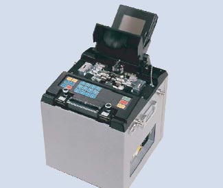
Sumitomo 35SE is one of the first automatic optic fiber splicers ( costed over 17K $ on launch ), supporting both multimodal and single mode fiber, and also edge cases like dissimilar diameter fibers or fibers with out of center core.
In this article we will go through some of the common faults you may find when you have a faulty one.
These machines are very well built so can in most of times be repaired easily.
No video
This will be one of the most common faults, symptom will be “LED WARNING” error and nothing at all on screen except text.
The issuse may also be accompanied by bad smell, which indicates blown electrolytic capacitors on video stage.
Before starting work check also with a flashlight if really the microscope is blind, othercause can be wrong mirror alignment.
To fix that issue you have to remove all side panels and then remove the camera from the microscope and the signal processing module, which is held by 4 hex screws on side (Sorry i don’t have for now a photo of that, but you can easily recognize it because camera cable goes in, another cable comes out going to main boards ).
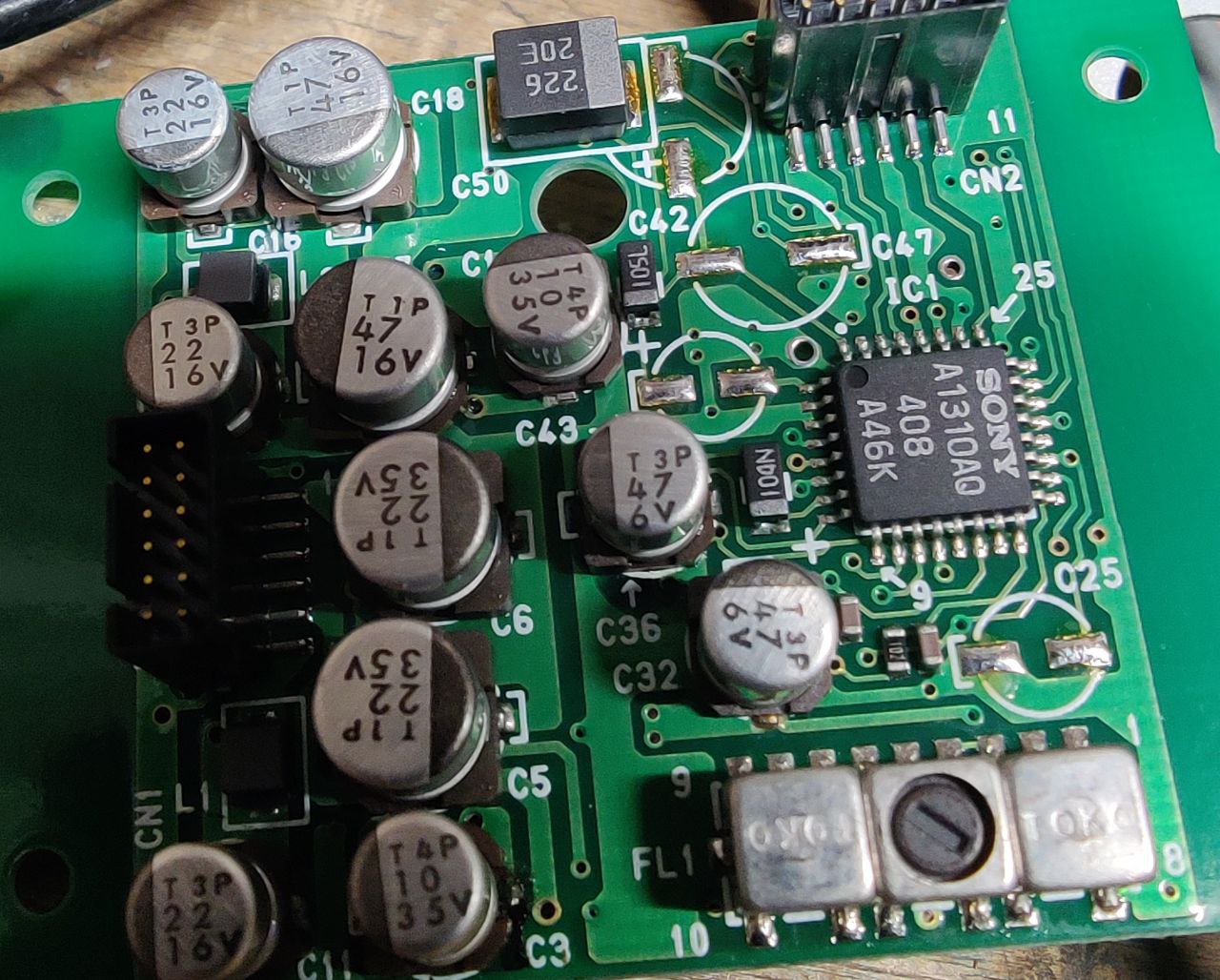
Once done you have to replace most if not all electrolytic capacitor on top board of the sandwitch, when repairing you can check on the first coaxial starting from +12V supply on the connector, you should see with an oscilloscope NTSC signal as soon properly repaired, especially if you shine a flash light on the CCD. If you do get a correct signal you are ready to reassembly it and start splicing.
Also when replacing them be sure to clean up any electrolyte leaked with isopropyl because it can corrode board.
Wrong brightness, LIGHT TEST not even close to 100
After reparing the camera, or simply over time, image may become darker or lighter.
To fix that you have to fiddle with the trimmer marked as “GAIN” on top board ( the one where you eventually replaced caps ).
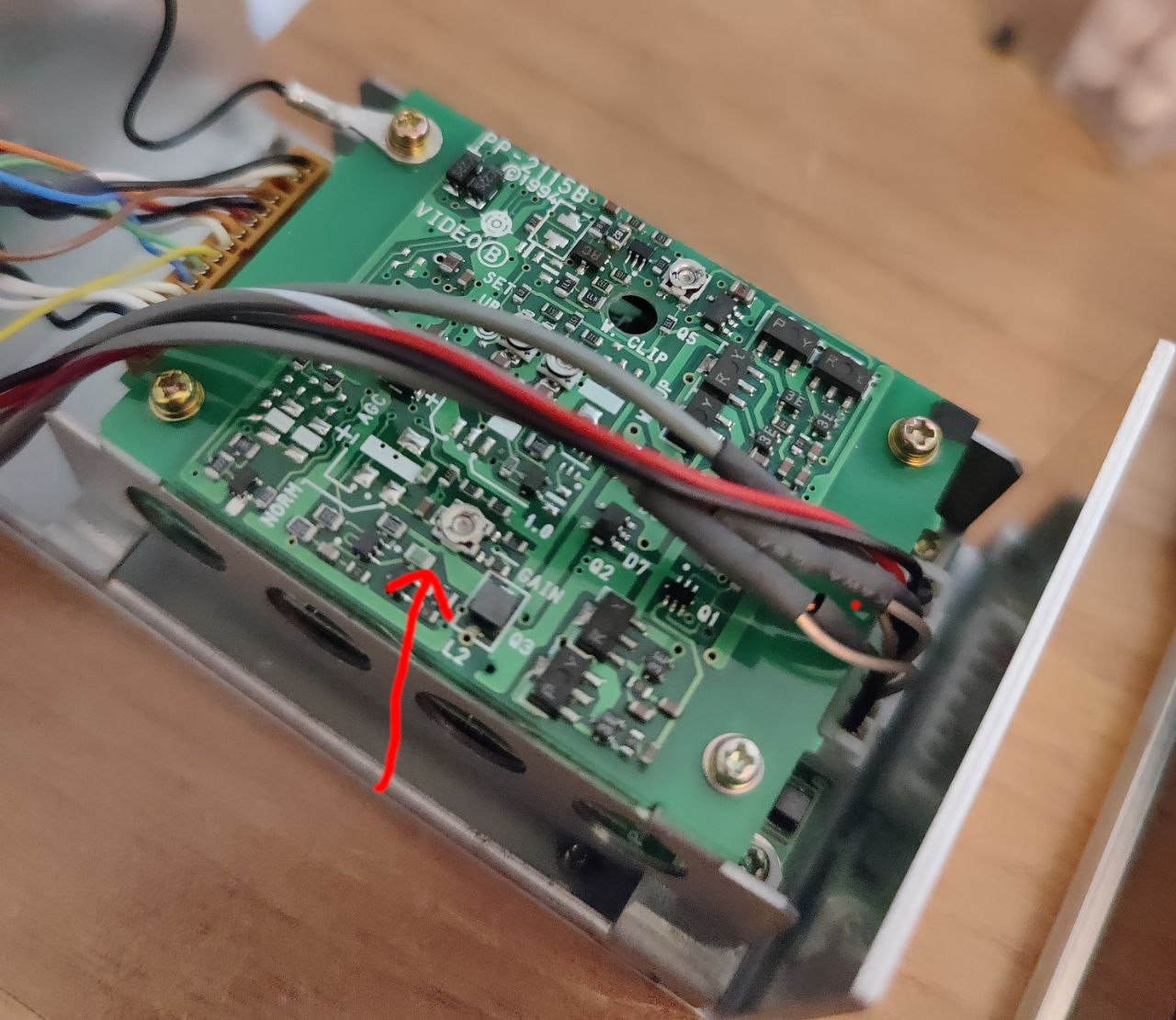
Before doing that be sure red LED is clean.
Beware trimmer can rotate all the way through, so you may reach a point where gain becomes instable because no contact , so be careful with it!.
Other two adjust black and white levels, usually not needed to touch them.
Set Error (L or R ) when starting splice or after first field change
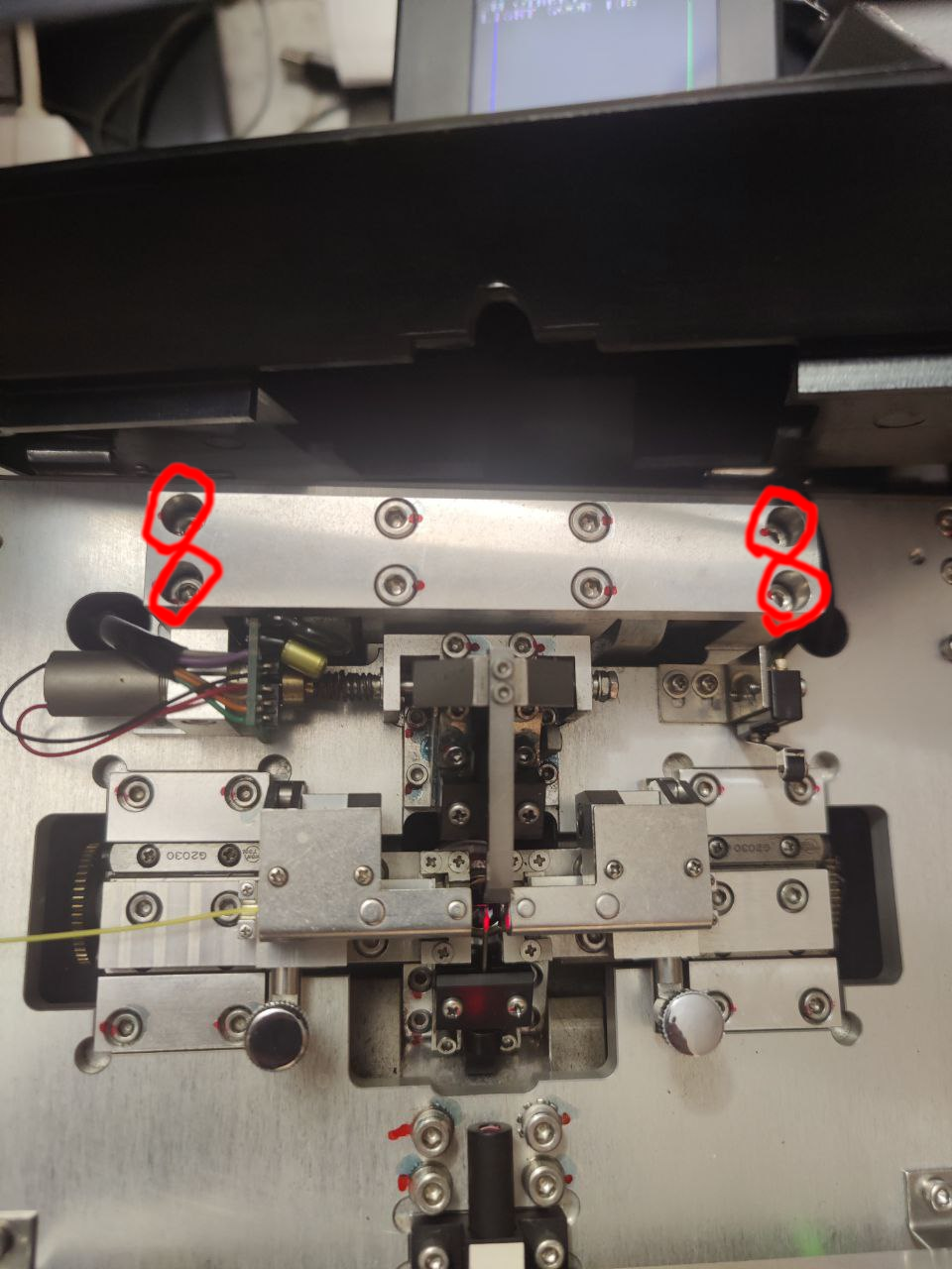
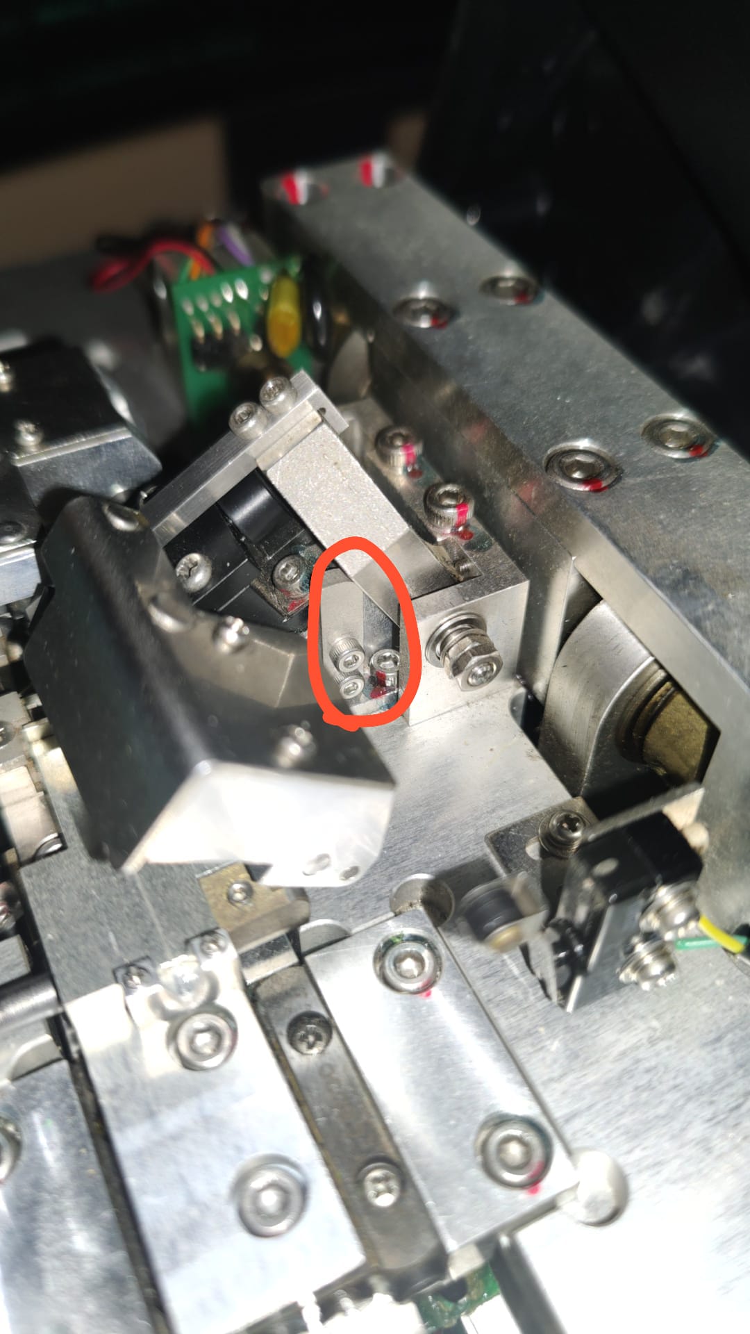
This is usually caused by bad mirror end alignment, can easily be fixed by repositioning the the small plate with two screws you can see in the picture .
To get it right i suggest placing a long piece of bare fiber that goes ALMOST, not all the way, from one V groove to the other, i said almost so if you accidentally move something it does not break.
After that switch to manual mode,and press SET button, this way the microscope positions itself on what should have that piece of fiber in view.
You can then adjust mirror stop to make it so it is in view. You may also need to make other adjustments then to make sure also when switchin fields it is still in view.
Also beware wrong mirror position CAN be a cause of low light condition, so broken microscope must be confirmed by shining a light to it.
Other issues
I have some stuff still to fix, like arc being offset from center, which requires reseating microsocope assembly, will add it to the article as soon done!
Update 1:
Fixing excessive arc offset from center
You can have a situation where when welding you see most of the glare coming from far left or from far right, and you can’t compensate it by setting electrode line from maintenance menu.
This is caused by wrong position of microscope assembly, to fix it follow this procedure:
- Remove top of the splicer ( 6 philips screws , be careful with display cables )
- Place a fiber on ONLY a side of the splicer, leave other side without fiber, try to splice, it will error out with a limit being hit, it’s ok. To start the splice without top cover, press the microswitch, beware to not come in contact with electrodes, they may come live with high voltage!!
- Now carefully loosen the 4 screws holding microscope assembly as shown in the image below
- Very slowly move either right or left the block where you loosened screws, while doing that press mirror down by hand and see on screen, you have to do your best to bring the spot where the arc was to the center of screen. ( it will take multiple attempts )
- Tighten screws in cross order like you would on a cpu or engine head to minimize accidental movement.
- Fine tune alignment position using arc line setting in maintenance menu
- In extreme cases you may need to readjust mirror position as shown above