In electronics projects, frequently we need an overvoltage protection, for example we have 200V of solars charging a battery, we may want as last resort if MPPT fails, and everything else fails a non destructive protection before a crowbar.
Other applications maybe in conjuction with a BMS to add extra security against overvoltage, other applications too may be interesting.
Standard options
Usually there are standard options with their respective drawbacks such as:
- Crowbar: It is fast, but it will result in blown fuse and potentially fire hazard, also parts used in the crowbar itself may be one time use only.
- Relay: Useable but we need a relay with proper coil voltage, contacts are not much guaranted to not get stuck, and requires an active circuit to prevent it from oscillating after being triggered.
- Mosfet: Delicate and requires active circuit
The epic contraption to do it reliable and quick
There’s that cheap device called residual current device (RCD), it works as shown in that diagram
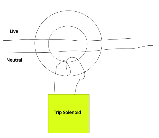
Under normal conditions, current in live and neutral wire is equal, so induced current to trip solenoid is zero.
If there’s a ground fault, for example someone touching live wire or touching phone while charging with faulty adapter, it will draw more current from Live wire than from neutral.
That imbalance will induce a current in the trip solenoid that in turn will trigger the disconnect mechanism.
The special characteristic of that solenoid is that it leverages a permanent magnet to be even more sensible, so a very very small current will trip it.
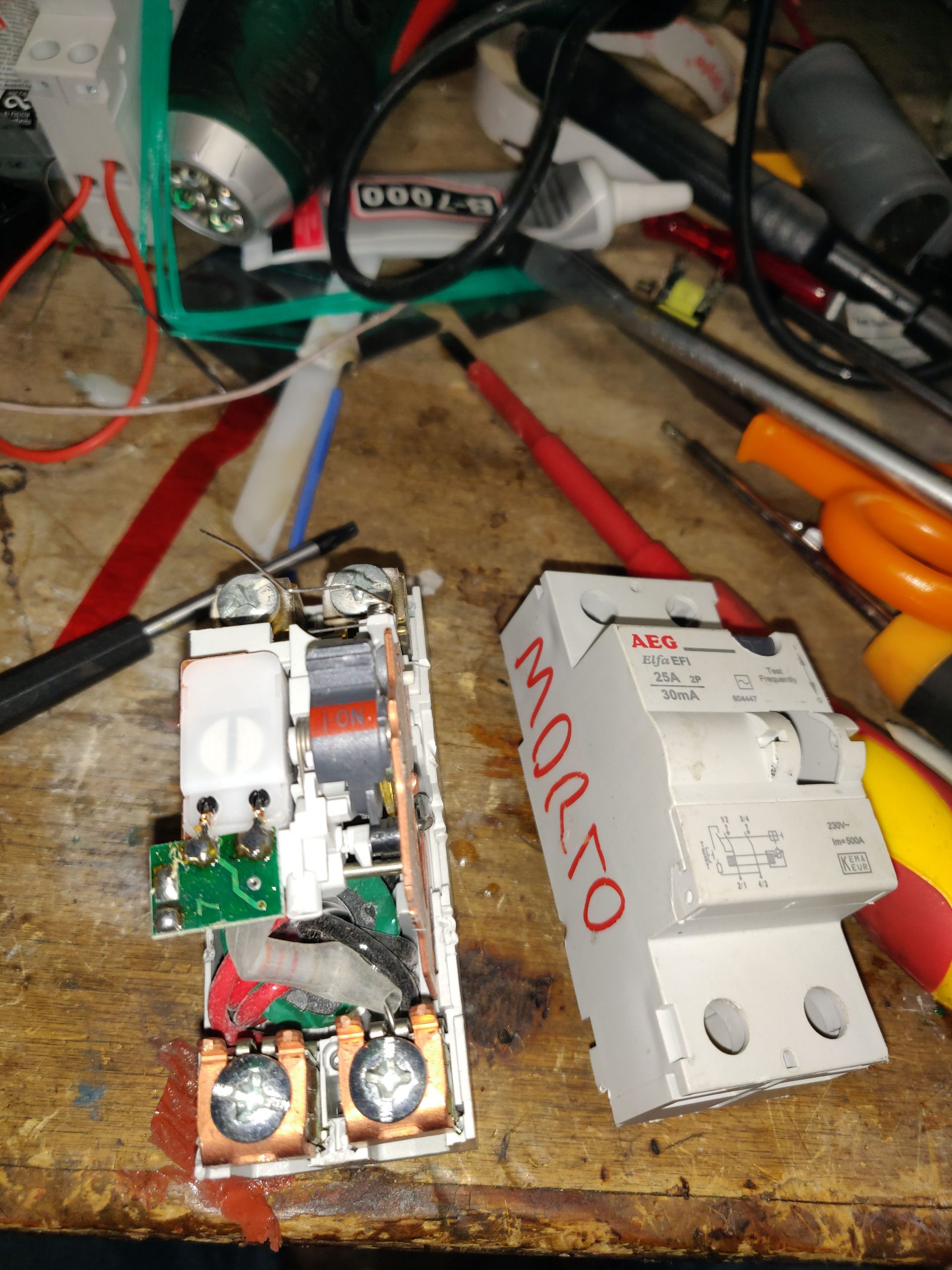
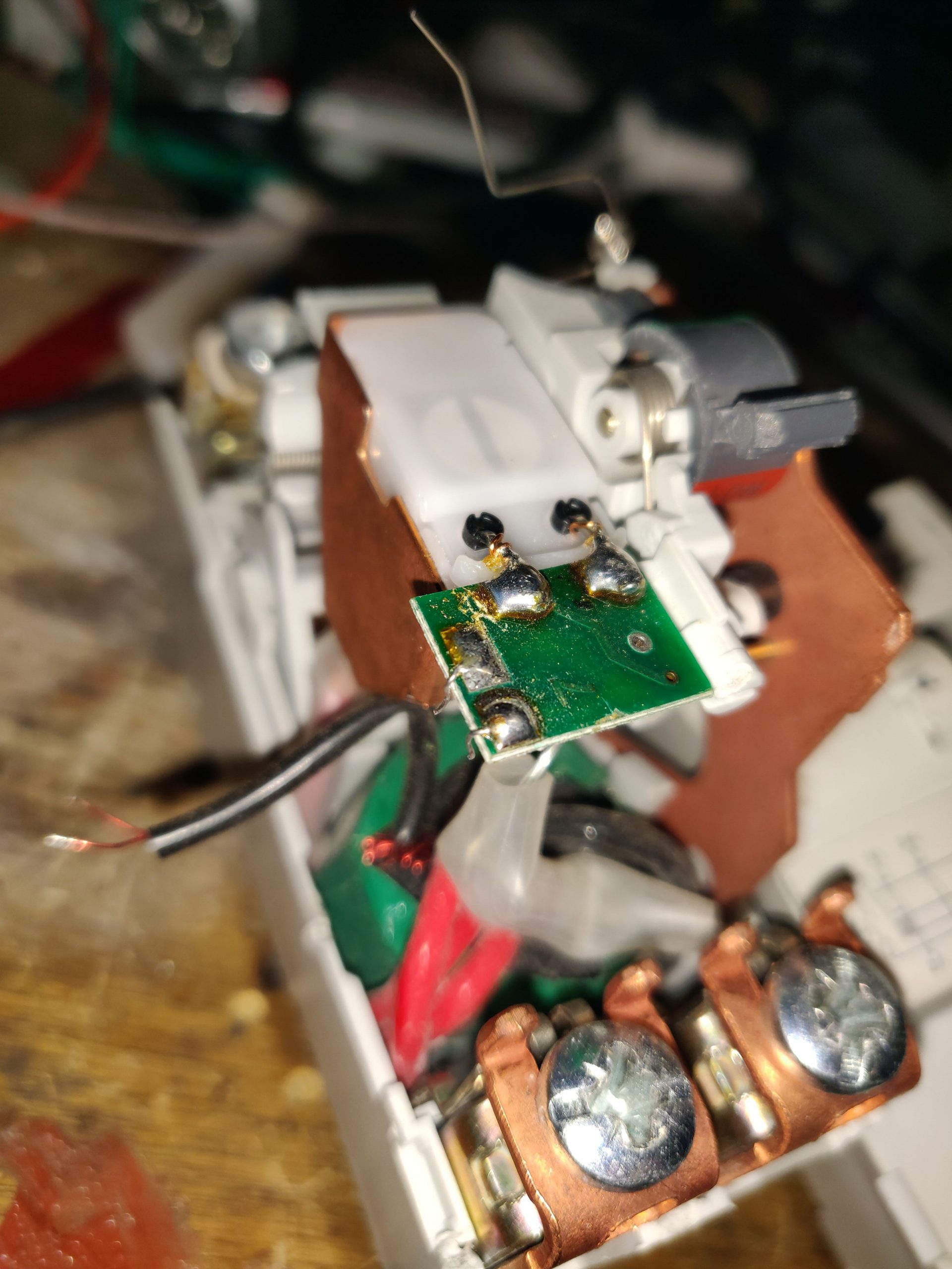
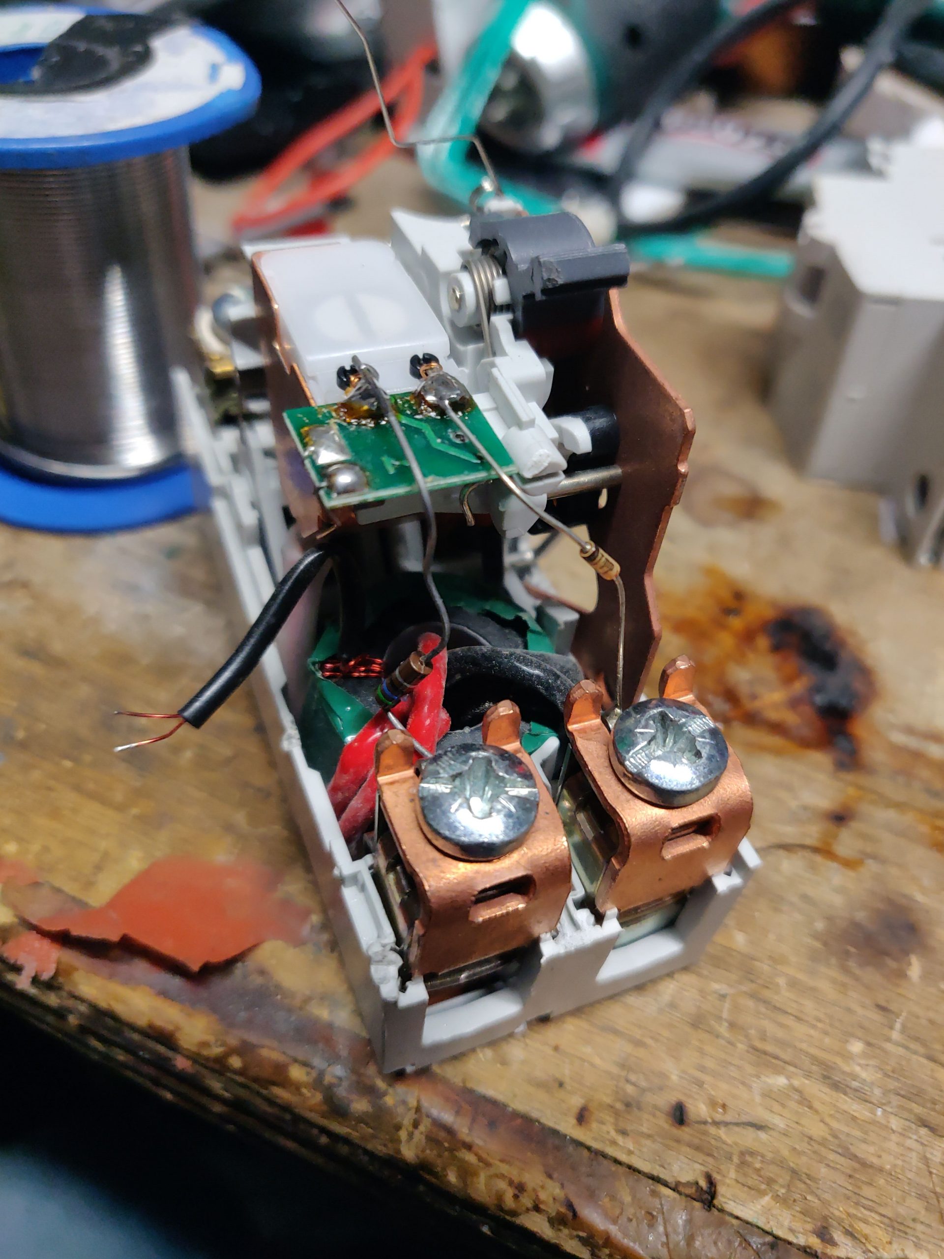
In this modification, we take apart the RCD , exclude the current transformer ( toroid ) by cutting the wires going to trip solenoid, and then drive them from output with a zener.
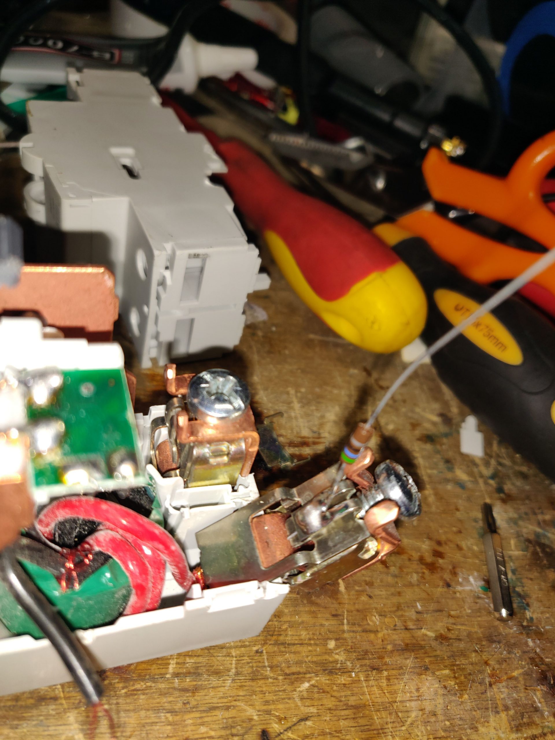
Beware that trip solenoid is sensitive to polarity ( that why these are labeled AC, they may not trip with DC fault ) , you have to experimentally find polarity with a small 1.5V button cell and that resistor, with correct polarity it will trip.
Next we have to pick a zener, the zener will be at what voltage we want the protection to trip, in our case for demonstration purpose we choose a 10V zener, pretty nonstandard useless voltage for protection.
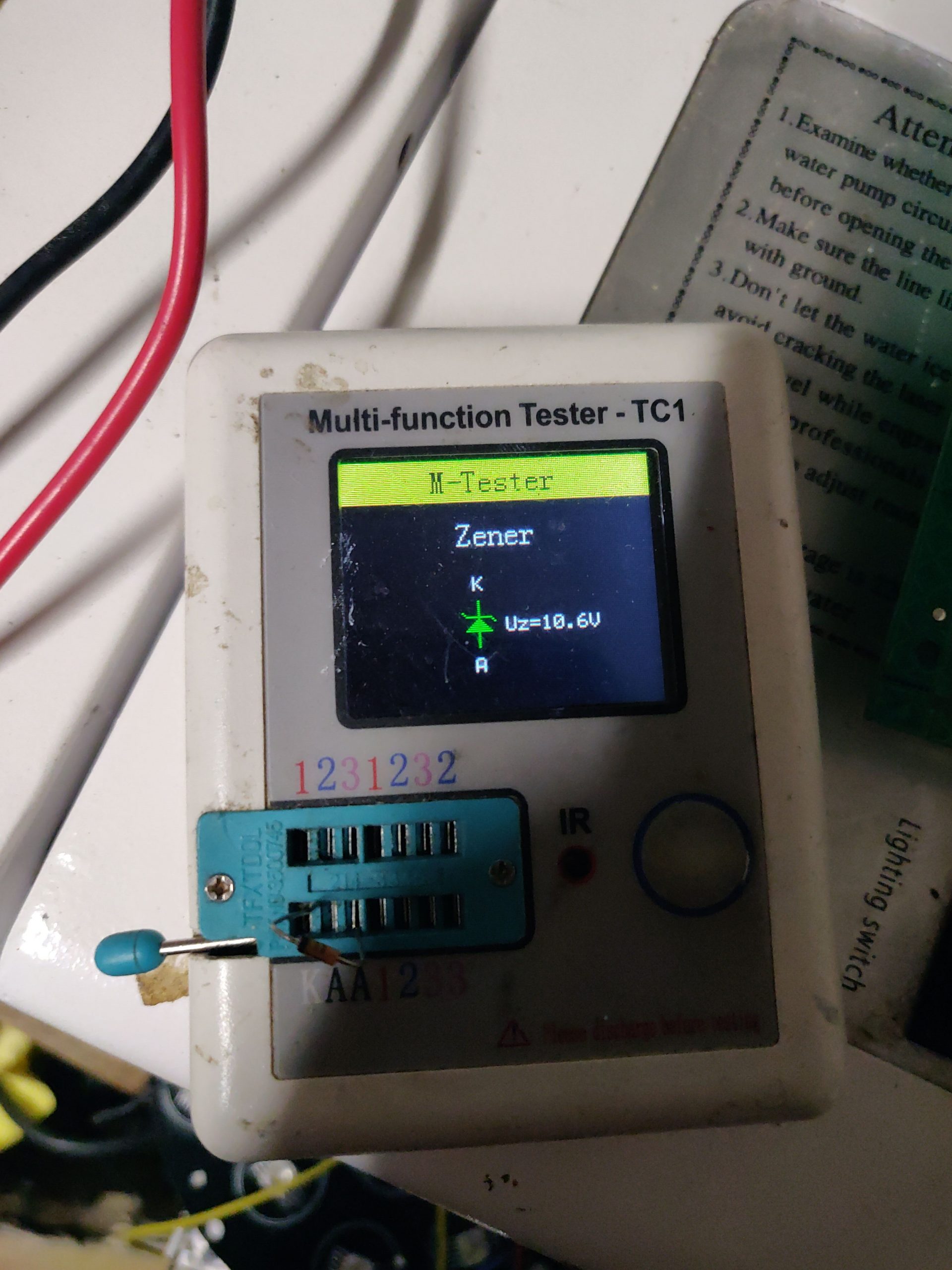
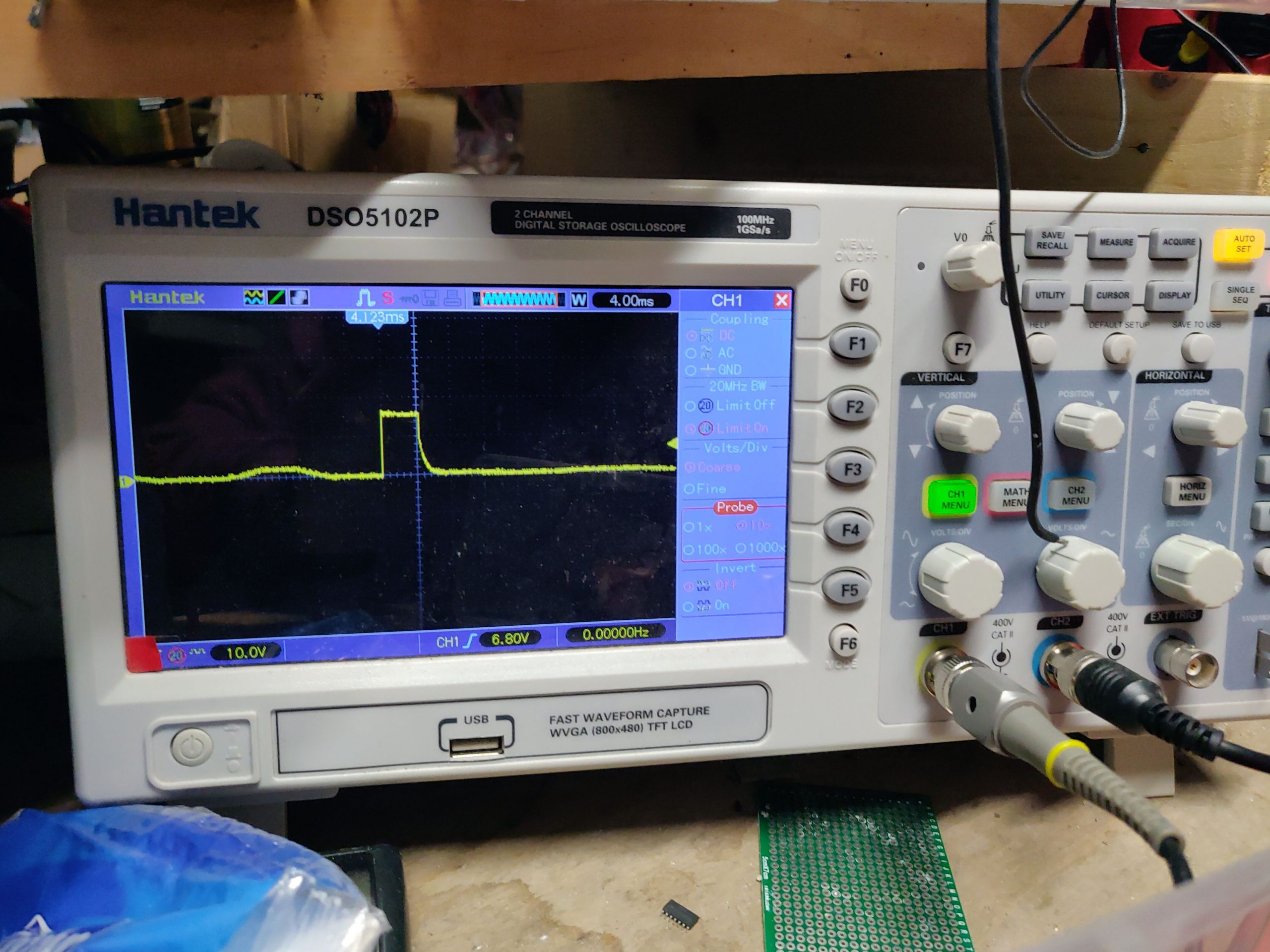
First test shows perfectly tripping at 10.6V as the choosen zener 🙂
A word of warning
This mod, altough it seems to work pretty well, it needs extensive field testing to assert its reliability, and also like with regular RCD one would need to test it regularly, unfortunately that won’t be easy after that mod, unless i add a button bypassing the zener, original test button will not work, so, never use that , but that is true with any protection, alone, always have at least 2, for example this set at 15V and a crowbar set at 17V.