It’s not unusual to end up with dead laptops whose battery is still useable for some other projects, the most usual practice, is to dismantle them to recover 18650 cells, but then you will have some prolems with integrating them on your project, the first one is avoiding stuff to catch fire or blow up and the second one is that you have no way to reliably tell how much % of charge is left on these batteries, and their real capacity ( capacity decreases with time and usage ).
These batteries in most cases are connected to an I2C/SMBus of the laptop and they use the Smart Battery protocol, which is a standard of most advanced battery powered systems, especially laptops.
The hardest part normally is to find the pinout of these batteries, but since Acer easily leaks complete motherboard schematics, it has not been hard to find these pinouts.
For now i’ve worked with a AL10B31 battery and a AS07B41 battery, they have different pinout, but both can be found on the respective schematics of the Quanta ZE6 and Quanta ZO3. One important thing to be careful about is that once you are using the connector from the motherboard outside the laptop, it’s easy to insert it reversed by accident and cause serious damage both to the arduino and to the battery itself.
Charging the battery and using it
The AL10B31 and AS07B41 batteries are both 11.1V , that means that there are 3 cells in series, so to charge them you have to use a CC-CV power supply with 12.6V ( 4.2*3 ) and at most 1.5-2 amperes.
The battery of the Acer Aspire One ( Quanta ZE6 ) has an additional safety measure that will prevent you from charging it by just applying 12.6V on it’s + and – terminals.
There’s the pin 3 that has to be connected to ground with a 1KOhm resistor to enable the battery.
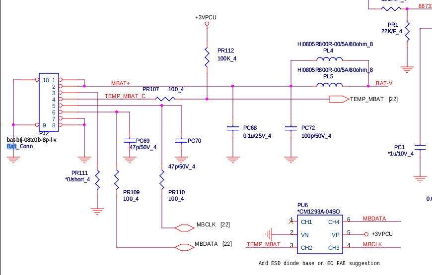 |
| Quanta ZE6 battery connector |
Even if in the above schematic it says “short”, i’ve used 1KOhm resistor because that’s the resistance i’ve measured on the netbook’s motherboard between this pin and ground.
The AS07B41 that has same pinout of the AS07A(31/32/41) used by Quanta ZO3 but reversed and it does not have any safety measure that remove power from it’s + and – pins if not connected to the laptop, so if you just want to charge it you are ready to go with 12.6V CC-CV and at most 2 amperes
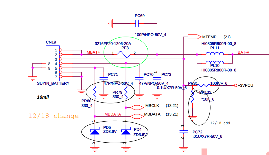 |
| Quanta ZO3 battery connector |
Connecting to and monitoring the battery with an arduino
SMbus and I2C are physically compatible with each other, so like in the laptops i2c devices and battery share same bus, you can use the battery almost like and i2c device.
The only problem is that arduino Wire library does not give you much control over speed and start/stop, so, you will have to use a software i2c library.
Before including the .h of the library ( if you are too lazy to put the library in a folder, like me , you can just paste the contents on you sketch ), you have to define which pins to use for software I2C.
#define SDA_PIN 3
#define SDA_PORT PORTD
#define SCL_PIN 2
#define SCL_PORT PORTD
#define I2C_SLOWMODE 1
On the arduino mega 2560 these are pins 19 for SCL ( MBCLK ) and pin 18 for SDA ( MBDATA ) .
You have also to define I2C_SLOWMODE in the case you have problems with communicating to the battery.
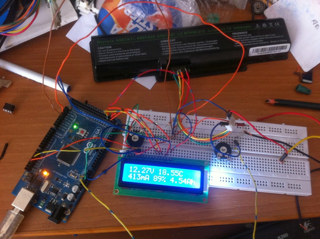
I’m using that sketch to read values from the battery:
LiquidCrystal lcd(12,11,50,51,52,53);
byte deviceAddress = 11;
#define VOLTAGE 0x09
#define TEMPERATURE 0x08
#define CURRENT 0x0a
#define CAPACITY 0x10
#define TIME_TO_FULL 0x13
#define CHARGE 0x0d
void setup()
{
lcd.begin(16,2);
//pinMode(22,INPUT_PULLUP);
//pinMode(23,INPUT_PULLUP);
Serial.begin(115200); // start serial for output
Serial.println(i2c_init());
//pinMode(22,INPUT_PULLUP);
//pinMode(23,INPUT_PULLUP);
scan();
}
int fetchWord(byte func)
{
i2c_start(deviceAddress<<1 | I2C_WRITE);
i2c_write(func);
i2c_rep_start(deviceAddress<<1 | I2C_READ);
byte b1 = i2c_read(false);
byte b2 = i2c_read(true);
i2c_stop();
return (int)b1|((( int)b2)<<8);
}
void scan()
{
byte i = 0;
for ( i= 0; i < 127; i++ )
{
Serial.print(“Address “);Serial.print(i);
bool ack = i2c_start(i<<1 | I2C_WRITE);
if ( ack )
Serial.println(“OK”);
else
Serial.println(“NO”);
i2c_stop();
}
}
void loop()
{
int v = fetchWord(VOLTAGE);
Serial.print(“Voltage: “);
Serial.println(v);
lcd.clear();
lcd.print((float)v/1000.0);lcd.print(“V “);
Serial.print(“Temp: “);
unsigned int tempk = fetchWord(TEMPERATURE);
float tempc = ((float)tempk)/10.0-273.15;
lcd.print(tempc);
lcd.print(“C”);
lcd.setCursor(0,1);
Serial.println(tempc);
Serial.print(“Current (mA):” );
int ma = fetchWord(CURRENT);
lcd.print(ma);lcd.print(“mA “);
Serial.println(ma);
Serial.print(“Capacity (mAh):” );
int mah = fetchWord(CAPACITY);
Serial.println(mah);
int ch = fetchWord(CHARGE);
Serial.print(“Charge PCT: “);Serial.print(ch);
lcd.print(ch);lcd.print(“% “);lcd.print(float(mah)/1000.0);lcd.print(“Ah”);
Serial.print(” Minutes remaining for full charge: “);
Serial.println(fetchWord(TIME_TO_FULL));
delay(5000);
}
I’ve omitted the beginning because it’s just the software i2c library and some includes like LiquidCrystal.h .
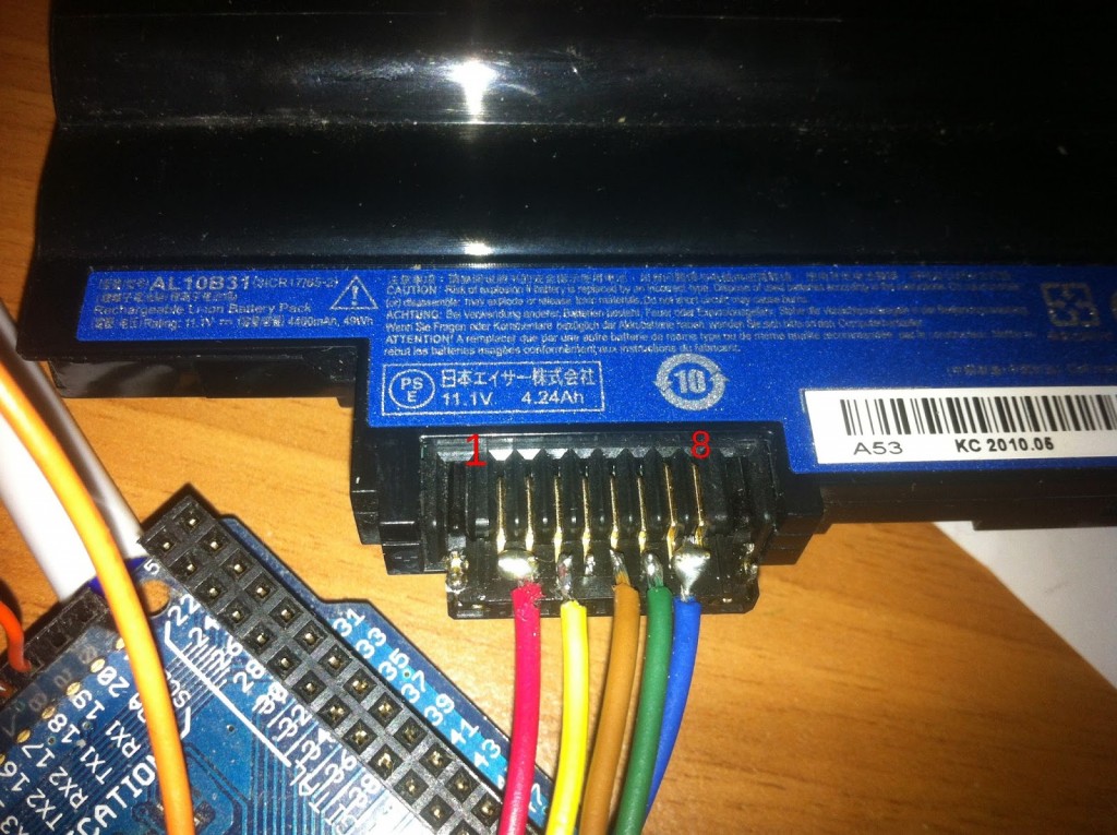 |
| Quanta ZE6 battery |
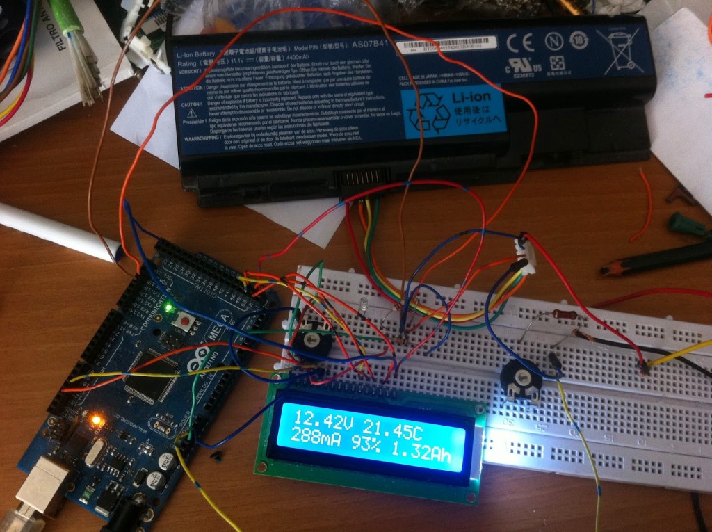 |
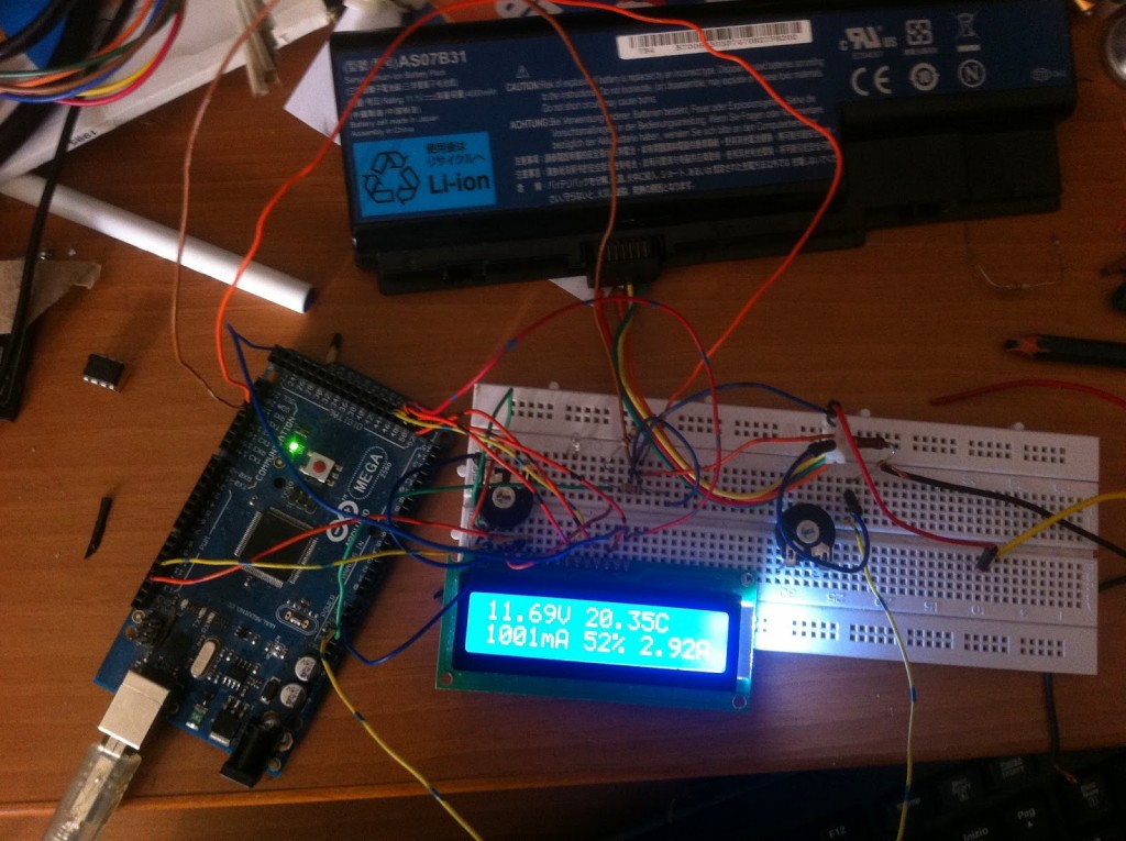
| Charging AS07B41 |
 |
| Charging AS07A(31,32,41) , Quanta ZO3 |
 |
| Charging AS07B31 ( Same pinout as AS07B41 ) |
On the hardware side instead, you have to connect the arduino ground to the battery ground ( BE VERY SURE IT IS THE BATTERY GROUND ) and SCL, SDA pins respectively to MBCLK and MBDATA pins.
You have also, as the master of the i2c bus provide the pullup, so you have to use 2 10K resistors connected between +5V and the SDA,SCL lines.
Once you enable the battery ( if required ) , you should be able to communicate with it using that code.
If you are interested on monitoring other parameters, like remaining time to 0%, design voltage , manufacture date , etc, you can see what is the ID to use here
http://sbs-forum.org/specs/sbdat110.pdf
Finally, i remind to who is going to use these batteries, that they have high energy density, so they can start a fire or explode if mishandled.
Edit: I’ve discovered that sometimes reading are wrong, lowering I2C frequency solves that issue , to do that modify
#if I2C_SLOWMODE
#define I2C_DELAY_COUNTER (((I2C_CPUFREQ/25000L)/2-19)/3)
#else
to
#if I2C_SLOWMODE
#define I2C_DELAY_COUNTER (((I2C_CPUFREQ/15000L)/2-19)/3)
#else

How do you control charging, by arduino or by an external charger?? Li Ion batteries need a dedicated controller for this and laptops have s special Maxim chip in charger section.
Excellent post and wonderful blog, I really like this type of interesting articles keep it u.
Visit this web site for more info
Hello!
Can you help me do the same thing. I have one Toshiba Satelite battery. I don't need the LCD monitor to look over the voltage and precentage. I will monitor them trough the Serial.
I want to achieve this result with Arduino Uno.
Please help 🙂
Have you tried looking up laptop's motherboard schematics?
Im tryng for a while now to do this but the library it doesn't work, on serial monitor appears only weirds characters, can u please help me with your original library that u used and sketch and send them to my email plss? im tryng to do this for a very long time, pls help me:( send pls at adycobra2003@yahoo.com
Now this is what I’m talking about. I’m looking to charge it that way. While the battery is powering arduino. Now the only way I know is taking a 12volt to 9 volt converter to make sure it doesn’t burn out the Arduino board. I don’t have the kit from amazon.com or parts for it. But it’s on my wish list.
If you would like to know: Its for a model rocket launch controller. I thinking about using arduino board and breadboards, a couple of keys to turn the power on and off. A toggle switch(To launch the rocket).
Now I have the power problem solved. How do I connect the battery to the toggle switch and the two keys?. While it’s connected to the Arduino board. Can you give me some ideas. I can give you my email address if you want it. Thanks.
oops I forgot to add: I’m using the barrel plug to power the arduino board. While it’s power the board. That’s why I’m thinking about using a 12 volt to 9 volt converter to connected to the battery the connect the barrel plug to the converter and then plug it into the arduino board. Sorry it’s kind of hard to explain. Here on this website.