The title of that post may look crazy at first, but it’s not, it is entirely possible to convert your cheap 100M 8 port switch or stuff like that to a managed switch.
That’s possible simply because, if you open up one of these and look at the datasheet, you will find out that they use the same switch chips used frequently inside of routers ( which they can be reprogrammed as you like with openwrt ).
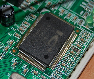
The switch i’ve used this time is a “digicom 10/100” switch, digicom is an italian rebrand of some other stuff probably, but anyway, let’s get straight to the point, below you can see the PCB of that switch
Switch chip is IP178CH, and since today luck is on our side, its datasheet can easily be found there http://www.icplus.com.tw/Data/Datasheet/IP178Cx-DS-R13-20080925.pdf .
 |
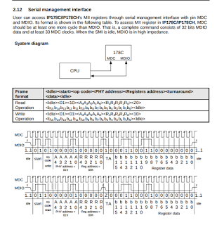
| Serial management interface timing diagram and command format |
Now by taking a quick look at the datasheet some important things for that modification are easily found:
- The switch chip can be programmed by pulling up or down it’s pins but only basic features are programmable that way
- The switch chip can be programmed from the EEPROM ( which on that switch board is not present, but there are unpopulated pads for it ), for the switch to take in account the EEPROM , first two bytes must be 0x55AA
- The switch chip can be programmed using a synchronous serial interface at pins MDC & MDIO, on the fly.
This one is the most useful one to create a managed switch
The serial interface is similiar to I2C but much simpler, it does not support multiple devices on the same bus and devices don’t have an address.
MDC Clock has to be generated from CPU side ( in that case an arduino ) , so you can operate it at whatever speed you want provided you don’t exceed maximum ratings.
Now once you know how to operate communicate with the switch it’s just matter of programming an arduino.
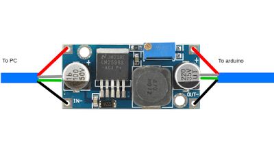
To do that, if you want just to test and you are going to power the arduino over usb. you are going to need to modify an USB cable to give arduino 3.3v instead of 5v.
You could also use a level shifter for that, but i prefer powering the entire arduino at 3.3v because it’s simpler and cheaper.
To power an arduino with 3.3v you can simple take an usb cable and cut red and black wires and insert a regulator between PC side and arduino side.
 |
| Arduino usb cable modification |
After doing that modification, just adjust the regulator to give 3.3v and you are ready to go
On that switch , since again , we are lucky today, the IC pins of the serial management interface were already routed to an unpopulated header, on which i soldered a 3 pin strip header
The pinout is the following:
1 : GND
2 : MDIO
3 : MDC
MDIO must be pulled high using a 2.2k resistor or some similiar value, again, if you are using a level shifter instead of the 3.3 cable mod, be sure to connect pullup resistor to 3.3v and not 5V.
To protect I/O lines also add two 100 ohm resistors or 200 ohm at most between MDIO,MDC and arduino pins ( 2,3 )
After doing that the HW part is done, if you want to make it permanent, just buy an arduino pro mini ( NOT NANO ) , and an usb-serial, the two should be around $2 total, max 3$.
You can also easily find on the board the 3.3v power rail and power the pro-mini from there, DO NOT power the arduino pro mini from usb or use an arduino nano or you will fry everything.
When connecting usb-serial adapter to it you will only connect GND, RX, TX wires , also DTS if you want to be able to program it from usb.
Now let’s take a look of a basic software to have a managed switch which can save configuration on arduino eeprom and restore it at boot.
|
1 2 3 4 5 6 7 8 9 10 11 12 13 14 15 16 17 18 19 20 21 22 23 24 25 26 27 28 29 30 31 32 33 34 35 36 37 38 39 40 41 42 43 44 45 46 47 48 49 50 51 52 53 54 55 56 57 58 59 60 61 62 63 64 65 66 67 68 69 70 71 72 73 74 75 76 77 78 79 80 81 82 83 84 85 86 87 88 89 90 91 92 93 94 95 96 97 98 99 100 101 102 103 104 105 106 107 108 109 110 111 112 113 114 115 116 117 118 119 120 121 122 123 124 125 126 127 128 129 130 131 132 133 134 135 136 137 138 139 140 141 142 143 144 145 146 147 148 149 150 151 152 153 154 155 156 157 158 159 160 161 162 163 164 165 166 167 168 169 170 171 172 173 174 175 176 177 178 179 180 181 182 183 184 185 186 187 188 189 190 191 192 193 194 195 196 197 198 199 200 201 202 203 204 205 206 207 208 209 210 211 212 213 214 215 216 217 218 219 220 221 222 223 224 225 226 227 228 229 230 231 232 233 234 235 236 237 238 239 240 241 242 243 244 245 246 247 248 249 250 251 252 253 254 255 256 257 258 259 260 261 262 263 264 265 266 267 268 269 270 271 272 273 274 275 276 277 278 279 280 281 282 283 284 285 286 287 288 289 290 291 292 293 294 295 296 297 298 299 300 301 302 303 304 305 306 307 308 309 310 311 312 313 314 315 316 317 318 319 320 321 322 323 324 325 326 327 328 329 330 331 332 333 334 335 336 337 338 339 340 341 342 343 344 345 346 347 348 349 350 351 352 353 354 355 356 357 358 359 360 361 362 363 364 365 366 367 368 369 370 371 372 373 374 375 376 377 378 379 |
#include <EEPROM.h> #define MDIO 2 #define MDC 3 #define PHY30_REG13_PORT1_REMOVE_TAG 0x10 #define PHY30_REG13_VLAN_EN 0x8 void outBit(int b) { digitalWrite(MDC,LOW); if ( b == 0 ) digitalWrite(MDIO,LOW); else digitalWrite(MDIO,HIGH); delayMicroseconds(1); digitalWrite(MDC,HIGH); delayMicroseconds(1); } int inBit() { digitalWrite(MDC,LOW); delayMicroseconds(1); unsigned int res = digitalRead(MDIO); digitalWrite(MDC,HIGH); delayMicroseconds(1); return res == HIGH ? 1 : 0; } unsigned int readReg(unsigned int phyaddr, unsigned int regaddr) { int k = 0; unsigned int res = 0; pinMode(MDC,OUTPUT); inBit(); inBit();//IDLE pinMode(MDIO,OUTPUT); pinMode(MDC,HIGH); outBit(0);//START outBit(1); outBit(1);//READ outBit(0); for ( k = 4; k >= 0; k-- ) outBit((phyaddr >> k) & 0x1); for ( k = 4; k >= 0; k-- ) outBit((regaddr >> k) & 0x1); pinMode(MDIO,INPUT); digitalWrite(MDIO,HIGH);//Pullup inBit(); //Z inBit(); for ( k = 15; k >= 0; k-- ) res |= ( inBit() << k ); return res; } void writeReg(unsigned int phyaddr, unsigned int regaddr, unsigned int value) { int k = 0; unsigned int res = 0; pinMode(MDC,OUTPUT); inBit(); inBit();//IDLE pinMode(MDIO,OUTPUT); pinMode(MDC,HIGH); outBit(0);//START outBit(1); outBit(0);//WRITE outBit(1); for ( k = 4; k >= 0; k-- ) outBit((phyaddr >> k) & 0x1); for ( k = 4; k >= 0; k-- ) outBit((regaddr >> k) & 0x1); outBit(1); //TA outBit(0); for ( k = 15; k >= 0; k-- ) outBit((value >> k) & 0x1); pinMode(MDIO,INPUT); digitalWrite(MDIO,HIGH); inBit(); inBit();//IDLE } void saveReg(unsigned int eebase, unsigned int phy , unsigned int reg) { unsigned int regval = readReg(phy,reg); EEPROM.write(eebase,regval&0xff); EEPROM.write(eebase+1,regval>>8); } void loadReg(unsigned int eebase, unsigned int phy , unsigned int reg) { unsigned int regval = 0; regval |= EEPROM.read(eebase); regval |= EEPROM.read(eebase+1) << 8; writeReg(phy,reg,regval); } void saveSettings() { int i; saveReg(2,30,13); for ( i = 0; i < 8; i++ ) { saveReg(4+i*2,30,3+i); } saveReg(20,30,12); for ( i = 0; i < 16; i++ ) { saveReg(22+i*2,30,14+i); } EEPROM.write(0,0x54); EEPROM.write(1,0x78); } void loadApplySettings() { int i; if ( EEPROM.read(0) != 0x54 || EEPROM.read(1) != 0x78 ) { Serial.println("Invalid settings found, loading defaults"); writeReg(30,13,PHY30_REG13_VLAN_EN); //Enable vlan for ( i = 3; i < 11; i++ )//All untagged packets from ports will have VID 1 by default { writeReg(30,i,0); } writeReg(30,12,0); //No port has tagged traffic by default writeReg(30,14,0x1ff); //All ports are member of VID0 (Untagged) for ( i = 15; i < 30; i++ )//A { writeReg(30,i,0); } saveSettings(); }else{ int i; loadReg(2,30,13); for ( i = 0; i < 8; i++ ) { loadReg(4+i*2,30,3+i); } loadReg(20,30,12); for ( i = 0; i < 16; i++ ) { loadReg(22+i*2,30,14+i); } Serial.println("Loaded settings from eeprom"); } } void setup() { Serial.begin(115200); Serial.setTimeout(60L*60L*1000L); pinMode(MDIO,INPUT); pinMode(MDC,INPUT); Serial.println("Waiting for the switch chip to start-up ( 10 secs)"); delay(10000); loadApplySettings(); } int getInt() { while( Serial.available() <= 0) {} char c1 = Serial.read(); int n1 = c1-'0'; Serial.print(c1); while( Serial.available() <= 0) {} char c2 = Serial.read(); int n2 = c2-'0'; Serial.println(c2); if ( n1 >= 0 && n1 <= 9 && n2 >= 0 && n2 <= 9 ) return n1*10+n2; else return -1; } unsigned int printPortMask(unsigned int current) { int i; for ( i = 0; i < 8; i++ ) { if ( (current >> i) & 0x1 ) Serial.print("y"); else Serial.print("n"); } } unsigned int inputPortMask(unsigned int current) { unsigned int n = 0; int i; Serial.print("Current ports (1-8 left to right):"); printPortMask(current); Serial.println(""); Serial.print("Insert new ports ( y = assign, n = not assign ):"); for ( i = 0; i < 8; i++ ) { char in; while ( 1 ) { in = Serial.read(); if ( in == 'y' || in == 'n' ) { Serial.print(in); break; } } if ( in == 'y' ) { n |= 1 << i; } } Serial.println(""); return n; } void loop() { int k; Serial.println("Arduino switch configuration"); Serial.println("0. Show current configuration"); Serial.println("1. Assign ports to a specified VID"); Serial.println("2. Select which ports should remove VLAN tag from outgoing packets"); Serial.println("3. Select which ports should add a VLAN tag to outgoing packets"); Serial.println("4. Assign a VID to untagged traffic from a port"); Serial.println("5. Show link status"); Serial.println("6. Load factory defaults"); Serial.print("Enter you choice:"); while( Serial.available() <= 0) {} int ch = Serial.read()-'0'; Serial.println(ch); if ( ch >= 0 && ch < 7 ) { if ( ch == 0 ) //Show current { Serial.println("VID Assignment ( 0 = untagged ):"); for ( k = 0; k < 16; k++ ) { Serial.print(k); Serial.print(" ports "); printPortMask(readReg(30,14+k)); Serial.println(""); } Serial.print("Remove VLAN tag ports: "); printPortMask(readReg(30,13) >> 4); Serial.println(""); Serial.print("Add VLAN tag ports: "); printPortMask(readReg(30,12)); Serial.println(); Serial.println("Default VID assignment for untagged traffic:"); for ( k = 0; k < 8; k++ ) { Serial.print("Port "); Serial.print(k+1); Serial.print(" untagged traffic will have VID "); Serial.println(readReg(30,3+k)); } } if ( ch == 1 ) //Assign ports to a specified VID { Serial.print("Insert VID(0-15) with a leading 0 if needed ( 04, 09, 13 , .. ):"); int vid = getInt(); if ( vid < 0 || vid > 15 ) { Serial.println("Invalid VID"); return; } unsigned int current = readReg(30, 14+vid); unsigned int newmask = inputPortMask(current); writeReg(30, 14+vid, newmask); if ( readReg(30,14+vid) != newmask ) { Serial.println("Can't set register value"); } saveSettings(); Serial.println("OK"); } if ( ch == 2 ) { unsigned int current = readReg(30,13) >> 4; unsigned int newmask = inputPortMask(current); writeReg(30, 13, PHY30_REG13_VLAN_EN | ( newmask << 4 ) ); saveSettings(); Serial.println(""); Serial.println("OK"); } if ( ch == 3 ) { unsigned int current = readReg(30,12); unsigned int newmask = inputPortMask(current); writeReg(30, 12, newmask ); saveSettings(); Serial.println(""); Serial.println("OK"); } if ( ch == 4 ) { Serial.print("Insert port (1-8): "); while( Serial.available() <= 0) {} int chp = Serial.read()-'0'; Serial.println(chp); if ( chp <= 0 || chp > 8 ) { Serial.println("Invalid port"); return; } Serial.print("Insert default VID for untagged traffic:"); int vid = getInt(); if ( vid < 0 || vid > 15 ) { Serial.println("Invalid VID"); return; } writeReg(30,3+chp-1,vid); saveSettings(); Serial.println("OK"); } if ( ch == 5 ) { for ( k = 0; k < 8; k++ ) { Serial.print("Port "); Serial.print(k+1); Serial.print(" Link "); int r = readReg(k,1); if ( (r >> 2) & 0x1 ) Serial.println("UP "); else Serial.println("DOWN "); } } if ( ch == 6 ) { Serial.print("Are you sure you want to load factory defaults ( y = yes ): "); while( Serial.available() <= 0) {} if ( Serial.read() != 'y' ) return; EEPROM.write(0,0x00); loadApplySettings(); } } } |
outBit and inBit generate a clock cycle on MDC while reading or writing an output value to/from MDIO
readReg reads an entire register by submitting read command, phy address and reg address
writeReg writes an entire register by submitting a write command together with phy address, reg address and the 16 bit value to write.
The switch itself works in a fairly simple way, you can assign which ports belongs to a VLAN ( that is independent from whether the packets will be tagged or not) and then you can configure how to treat untagged packet and what to do when a packet from a VID port group goes out of a port.
For example if you want to use port 1 as trunking port ( multiple vlan tagged networks on the same physical port ) , and you want to tag untagged traffic from ports 2,3,4 with vlan ids 2,3,4 you have to:
- Assign ports 1,2 to VID 2
- Assign ports 1,3 to VID 3
- Assign ports 1,4 to VID 4
- Set ports 2,3,4 to remove VLAN tags from outgoing packets
- Set port 1 to add VLAN tag to outgoing packets
- Set default VID for untagged traffic of port 2 to 2
- Set default VID for untagged traffic of port 3 to 3
- Set default VID for untagged traffic of port 4 to 4
With that configuration for example you will be able to connect 3 different networks to a single ethernet cable, which may be useful when you have a radio tower with multiple devices on it and only a single cable going to the ground equipment.
That’s just the beginning, similiar mods can in most of the cases be done on all switches and probably with more features on newer ( gigabit ones ) switches.
You could also use a raspberry to manage the switch instead of an arduino to be able to work on it from ethernet with some nice web interface.


